3 Bit Synchronous Counter Truth Table
A2 A1 A0. The circuit of the 3-bit synchronous up counter is shown below.
Solved Design A 3 Bit Counter Which Counts In The Sequence 001 Chegg Com
Draw the logic diagram of the synchronous counter.
. We want to be able to pause the counter rather than always incrementing every clock cycle so the slowena input indicates when the counter should increment. Build a decade counter that counts from 0 through 9 inclusive with a period of 10. The procedure to design a synchronous counter is as follows.
Truth Table Synchronous counters. Counter which counts 0000 BCD 0 to 1001 BCD 9 is referred as BCD or Binary-coded Decimal counter. Truth table for simple decade counter.
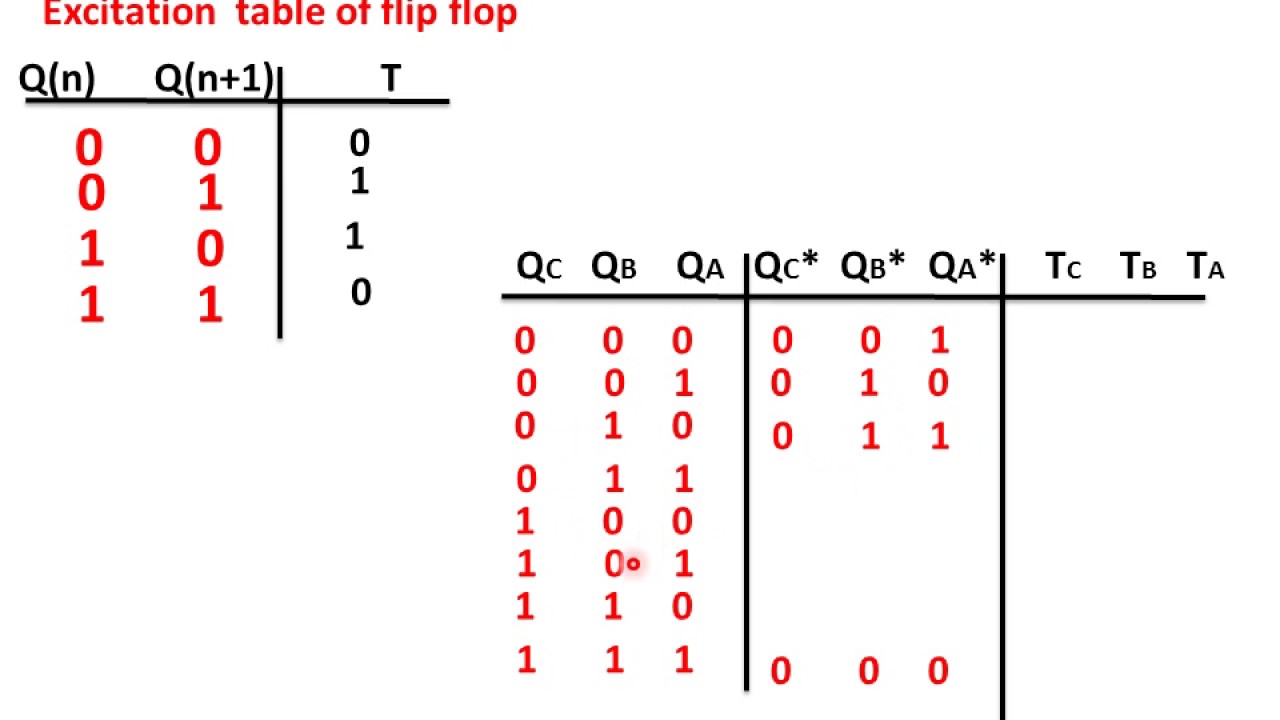
Choose the type of flip flop. Timing Diagram of Asynchronous Decade Counter and its Truth Table In the above image a basic Asynchronous counter used as decade counter configuration using 4 JK Flip-Flops and one NAND gate 74LS10D. Draw the excitation table for the counter.
Build a 64-bit arithmetic shift register with synchronous load. Derive the flip flop input functions using K-map. Decade counter circuit diagram.
Y7 to Y0 and 3 outputs. So FF-A will work as a toggle flip-flop. 3-bit synchronous up counter.
Consider the partial implementation of a 2-bit counter using T flip-flops following the sequence 0-2-3-1. A 3-bit counter consists of 3 flip-flops and has 2 3 8 states from 000 to 111. 3 Encoder Octal to Binary The 8 to 3 Encoder or octal to Binary encoder consists of 8 inputs.
Draw the state diagram of the counter. Another way of thinking about an arithmetic right shift is that it assumes the. The J A and K A inputs of FF-A are tied to logic 1.
The Truth table of 4 to 2 encoder is as follows. A1 Y3 Y2 A0 Y3 Y1 The above two Boolean functions A1 and A0 can be implemented using two input OR gates. 2-bit Synchronous up counter.
If the clock pulses are applied to all the flip-flops in a counter simultaneously then such a counter is called as synchronous counter. The clock pulse is given for all the flip-flops. The shifter can shift both left and right and by 1 or 8 bit positions selected by amount.
Logical expression for A1 and A0. Design and Verify the 4-Bit Serial In - Parallel Out Shift Registers Implementation and verification of decoder or de-multiplexer and encoder using logic gates Implementation of 4x1 multiplexer and 1x4 demultiplexer using logic gates Design and verify the 4- Bit Synchronous or Asynchronous Counter using JK Flip Flop. Synchronous up Counter counts the number of clock pulses at its input from minimum to maximum.
An arithmetic right shift shifts in the sign bit of the number in the shift register q63 in this case instead of zero as done by a logical right shift. Choose the number of flip flops using 2n N. The reset input is synchronous and should reset the counter to 0.
The J B and K B inputs are connected to Q A.
3 Bit Synchronous Up Counter ह न द Youtube
How To Design A Synchronous Counter Using D Type Flip Flops For Getting The Following Sequence 0 2 4 6 0 Quora
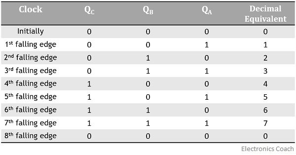
Truth Table For 3 Bit Asynchronous Counter Electronics Coach
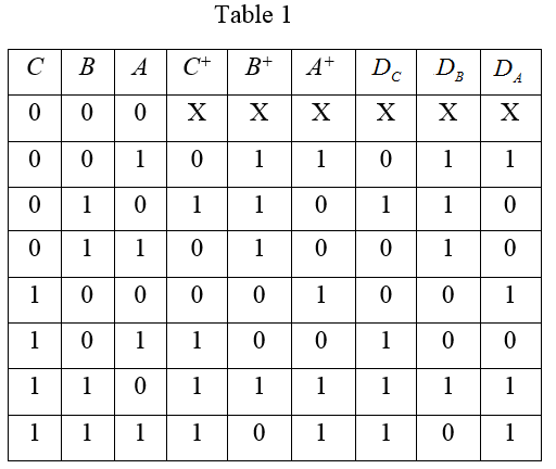
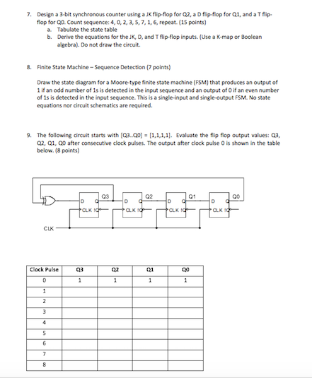
Solved 7 Design A 3 Bit Synchronous Counter Using A Jk Chegg Com
No comments for "3 Bit Synchronous Counter Truth Table"
Post a Comment